Zenith Aircraft Builders and Flyers
Online Community of Zenith Builders and Flyers
Toubleshooting First Start Jabiru 3300
Yesterday, I did the first start of the Jab 3300 in my CH 750. I rigged a 5 gal poly tank on top of the fuselage and plumbed it into the plane's fuel system where the wing tank will connect at the wing root. I turned the console mounted Andair fuel selector to left tank and it took about 2-3 seconds for fuel to gush from the gascolator on the firewall, so looks like the Earl's AN6 braided stainless is going to flow well! (I'll, of course, do a formal flow test later when the wing tanks are connected.)
I was very gratified that the engine started in less than 2 seconds! Not bad for a first try! It ran fine but I accidentally killed it by pulling the throttle back - the idle was set too low.
The engine is really smooth and has a great sound! I did have several gremlins pop up, however:
(1) I immediately noted that the tach (GRT EIS) wasn't right. The EIS documentation says "Jabiru 6 cylinder engines produce 4 pulses per revolution." The tach was unstable below 1000 rpm and often would read 0. A little web searching revealed that later Jabiru 3300's have a single phase alternator that produces 6 pulses per rev. When I set the "Tach P/R" to 6 - the tach worked great! GRT needs to update their documentation!
(2) When I had cranked the engine without fuel and plugs to pre-oil it before first start, the oil pressures looked normal for that situation. However, at first start, the pressure went to "80" and stayed there, no matter what the rpms, idle, etc. It only fell to zero at shut down. Again, a little searching reveals this is a common failure mode for the sender - so looks like a new sender is in order. Can anyone recommend a more reliable sender?
(3) Once I had the engine warm and stabilized at 1400 rpm, 4 cylinders had EGT's of 1114-1152 - a pretty nice, tight spread on a new engine! However, #3 indicated 357 degrees F and #2 indicated 831 !!! These probes accurately indicated ambient temperature and would start to rise at start-up with the others, but quickly lagged and never would get above these levels no matter what the engine rpm, etc. I pulled the plugs and checked them and they were fine. While the engine was running, I also checked the temp of the exhaust manifolds with a laser thermometer and they were the same as the others. Has to be bad probes? I'll see what GRT support says.
Just thought I'd post this in case anyone thinks I should be considering other solutions!
Thanks,
John
Replies to This Discussion
-
Permalink Reply by Phill Barnes on
-
Hi John
Have you checked the senders in an electric kettle? they should read 212 F at boil.
If exhaust gasses leak aroun the plug they can give erratic and false reading. Ring senders should be installed plug-sender-plug washer. When the plugs are installed, make sure that the sender stays central. Failing that, the photo below is what I did and mimmicks what Jab Aust do on their demo planes and at customer request. This was the original intended use for this hole but a sender was never develloped.
Hope I have helped a bit
Phill
Modified an 8mm flush trimming router bit with a pilot that fits neatly into the hole between the spark plugs. It is designed to take off some of the metal at the bottom of the hole to creat a bigger flat for terminal mounting. Drilled out the hole to 9/64" and then threaded the hole to an 8/32 thread. Crimped the new terminals on and screwed them down. 
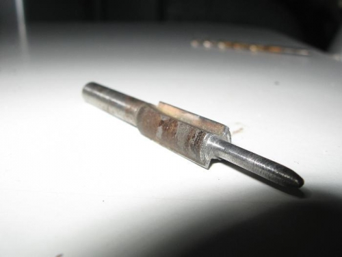
8mm flush trim router bit bored to accept a 1/8" pilot shaft to increase the flat around hole for cht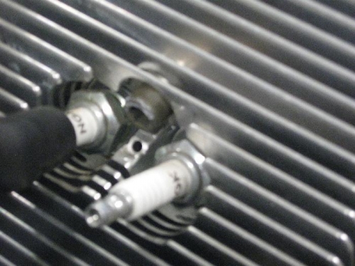
This hole was designed by Jab engineers as a cht pickup but a probe was never designed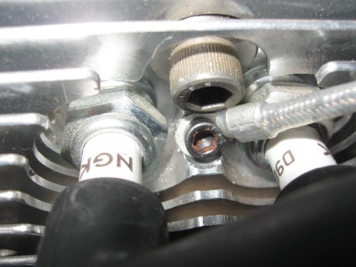
Threaded to an 8/32 thread. Some engines have had this mod done at Jab factory at customers request
-
Permalink Reply by John Austin on
-
Hi Phil!
Perhaps I wasn't clear, but the indicated readings of #3 of 357 F and and #2 of 831 F are EGT's, not CHT's. Again, my observations:
(1) The engine runs very smoothly and idles with no problems at 800 rpm.
(2) The EGT probes are exactly 120mm from the exhaust flange on every manifold and don't leak.
(3) The spark plugs were pulled and look exactly the same as those in cylinders with normal EGT's.
(4) Infrared laser readings of the manifolds are similar on all 6 cyl.
(5) CHT's are normal on the cylinders with the low EGT's.
(6) At 1400 rpm, all the other cylinder's EGT's are between 1114-1152 F.
Therefore, aren't these readings impossibly low and probably indicate defective EGT probes???
Regards,
John
(By the way, that's a slick CHT probe mod! I'm putting that on my list for next winter!)
-
Permalink Reply by Don Burkholder on
-
Hi, Did you try switching probe connectors? You say cht's are normal, what are they? Have you tried full power briefly to note the egt reaction. When viewed from side, make sure the carb isn't hanging down , or tilted up even by the slightest amount. Rotating the carb to correct for egt imbalance side to side is always mentioned, just make sure It's dead on when viewed from side...... Don
-
-
Hi Don,
I haven't tried switching connectors yet - the way the wiring is secured, I'll have to fabricate some extensions to accomplish that (not on the probe side of the wiring, of course). I felt that 357 was an impossibly low EGT in an apparently normally-running engine - if the temps were "real" at 357 and 831, that would mean two cylinders that were very badly off - I can't imagine this engine could run so smoothly if two cylinders were that far out. I haven't touched the carb's position - it's just as it came from the Jabiru dyno. It appears perfectly level and not rotated. I do have the SCAT air intake hose, but I did achieve a very smooth bend - it's even straight for a few cm prior to the carb and not bunched up.
I probablly shouldn't have said the CHT's are "normal" because I have no good reference since this is a ground run of a new engine! I "assume" they're normal - at least they seem "reasonable" - The temps ranged from 204-300 F. I thought these sounded about right? Of course, there are soooo many variables - new engine, uncowled, ambient temp, unmodified ram air ducts, etc. The #3 cylinder was 256F CHT (831 EGT) and this was warmer than the "normal" #1 cylinder opposite it (224F CHT, 1114F EGT)). I simply can't believe the EGT of 831!
Like I said - this engine to all appearances and sounds is running GREAT! I'm going to hit up GRT for new probes - they may make me test by swapping as you suggest - just trying to disturb as little as possible otherwise.
Thanks,
John
-
-
Hi John, I did forget to mention that the scat hoses are notoriously a problem with obtaining smooth airflow that the sensetive Bing needs. I have a rubber hose that gives a straight shot for about 4 inches. Try an auto store for your application. Some say try it without the scat hose as a test to see if your distributuion improoves, be carefull as there is no filtration. Do you have enough room to swap #3 etc etc??...Don
-
-
I can't believe it's a mixture distribution problem since it runs so well! It would seem logical to swap the probes and resolve whether it IS a probe problem or not. If the probes indeed are defective and I get balanced/normal readings after replacement, there will be no need to disturb the induction system. If, however, the EGT's are off (I just can't believe they could be that far off on 2 cylinders with all the other positve evidence of a healthy engine!), then obviously I'll tinker with the air flow delivery.
Thanks,
John
-
-
Hi John
Sorry about the egt cht mix up. I should have read a little more careful. On another observation that you have probably picked up on, if your cht's are all good then it is definately a probe or parrameter issue because egt's are what are the creator cht's.
Phill
-
-
That's one thing I noticed - one of the lower EGT's had a higher CHT than some of the other cylinders ... that didn't make sense. Also, all the exhaust manifolds were all about the same external temp.
I'm glad about the mix-up - I got to see your CHT mod! Very nice!
Regards,
John
-
-
I talked to Pete at Jabiru USA today - the oil sender was a simple fix! I had connected the sensor wire to the wrong terminal! There are two terminals, marked "W/K" and "G". I naturally assumed "G" was for "Ground", and knowing the sender is grounded to the engine block, I connected to "W/K" - WRONG! "G" stands for "Gauge" - duh!!! Pete said the "W/K" is an on/off switch and will give a full scale reading if erroneously connected.
Pete also provided some insight into the EGT's. He said he doubted 2 probes would be bad, and he agreed with me that those EGT's are NOT compatible with a normally-running engine such as mine. He therefore felt it was still an instrumentation problem - he said if the engine was really only running correctly on 4 cylinders out of 6, it would be shaking and vibrating unbelieveably! This engine is smoooooth!
He said that typically erroneously low EGT's like this are due to a faulty connection in the wiring harness between the probes and the EIS. He said many times the pins aren't seated well in the D-sub connector shell on the back of the EIS.
Sooo, I tried a little experiment - I switched the harness leads between the two affected cylinders, and sure enough the readings did not switch! That tells me it is NOT the probes themselves. I'm still waitng to hear from GRT to see if they agree. My biggest concern right now is if it is a connector problem - is this something I can field-repair? I'd sure hate to have to swap out harnesses and completely rewire the engine instrumentation!!!
And so it goes...
John
-
-
Hi John, It sounds like you're making progress. As you said, the readings didn't switch, the display still showed the cold and normal egt's in the same orientation as before. It would be interesting to see the layout of the EIS connector harness and note if cylinders 2 & 3 are at the end of the connector. If so, perhaps tightening that side will do. The other option that I would check first is the harness side connectors where you performed your test. Hopefully you will find a bad crimp where It's easy to get to...Don
-
-
PROBLEM RESOLVED!
I worked back to the D-sub connector on the GRT EIS and then I remembered I was the one who had assembled it! The harness was pre-wired, but you had to put the plastic shell on yourself - I also remembered that the metal clamp inside the shell that provides strain relief was very difficult to clamp around the wires since it is such a thick bundle.
I opened up the shell on he connector, removed the metal clamp, and sure enough - there was a cut in the insulation on one wire and a couple of other wire's insulation looked abraded. I think the metal clamp cut the wires and shorted them.
I wrapped the cut wire with electrical tape and then taped the whole bundle and left the metal clamp off. The plastic shell grasps the wrapped wires plenty firmly for strain relief ... and nobody's going to be yanking on them, anyway!
Fired up the engine and all EGT's were perfectly normal on all cylinders! I'm using the SCAT tubing in the induction, but I've got a very tight spread at 1400 rpm - all the EGT's were within a 50 deg F band, so looks like good mixture distribution.
New from Zenith:
Classified listing for buying or selling your Zenith building or flying related stuff...
Custom Instrument Panels
for your Zenith:
Custom instrument panels are now available directly from Zenith Aircraft Company exclusively for Zenith builders and owners. Pre-cut panel, Dynon and Garmin avionics, and more.
Zenith Homecoming Tee:
Flying On Your Own Wings:
A Complete Guide to Understanding Light Airplane Design, by Chris Heintz
Builder & Pilot Supplies:
Transition training:
Aircraft Spruce & Specialty for all your building and pilot supplies!
How to videos from HomebuiltHELP.com
Developed specifically for Zenith builders (by a builder) these videos on DVD are a great help in building your own kit plane by providing practical hands-on construction information. Visit HomebuiltHelp.com for the latest DVD titles.
© 2026 Created by Zenith.Aero.
Powered by
![]()